How Does a Three Phase to Single Phase Converter Work?

Understanding how a three phase to single phase converter works begins with a practical question: how can three coordinated voltage waves produce one dependable output? A three-phase supply carries three alternating currents, separated by 120 electrical degrees. The converter measures, switches, combines, or transforms those phases to create a controlled single-phase waveform. The exact method depends on the equipment design.

Power-electronics authority Ned Mohan describes the field this way: “Power electronics is the technology associated with the efficient conversion, control, and conditioning of electric power by static means.” That principle explains the converter’s main job. A static design may use rectifiers, capacitors, insulated-gate transistors, and an inverter stage. First, the incoming AC can become DC. Then, electronic switches rebuild a single-phase AC output at the required voltage and frequency. Some systems use transformers for isolation or voltage adjustment. Others use controlled phase selection, although that approach can create imbalance and waveform distortion.

The details matter.

In a workshop, the result may power a single-phase motor, heater, or machine controller. You might hear a faint switching tone and see a steady output voltage on a meter. However, a meter alone cannot reveal every harmonic or transient. Installation experience shows that load type, starting current, grounding, cooling, and protection ratings all influence performance. A three phase to single phase converter is not automatically efficient, balanced, or suitable for every motor. That assumption is tempting, but incomplete. This guide examines the conversion stages, switching behavior, waveform quality, and practical limits, while recognizing that real installations rarely behave as neatly as diagrams suggest.
How Does a Three Phase to Single Phase Converter Work?

What a Three-Phase to Single-Phase Converter Is

What a Three-Phase to Single-Phase Converter Is

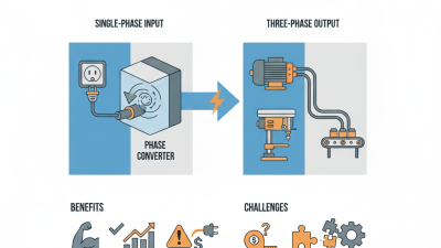
A three-phase to single-phase converter changes electrical power for equipment designed for one phase. It accepts three alternating voltage waveforms, spaced 120 degrees apart, then produces one usable output waveform. The output may come from one selected phase, a transformer, a rectifier, or an inverter stage. The design depends on voltage, frequency, load size, and required waveform quality.

Three-phase supplies can deliver power more evenly than single-phase supplies. A converter must still manage current carefully. If it draws heavily from only one phase, upstream conductors may become unbalanced. That creates extra heating and can disturb nearby motors. According to the U.S. Department of Energy’s Motor Systems Market Assessment, motor-driven systems once represented about 68% of industrial electricity use. The figure is dated, but it shows why conversion losses deserve attention.

Efficiency is not automatic. A transformer-based unit may be simple and quiet, while an electronic converter can regulate voltage more precisely. However, electronic switching may introduce harmonics, electromagnetic noise, and standby consumption. The International Energy Agency’s Electricity 2024 report expects global electricity demand to grow by 3.3% in 2024, increasing pressure to use conversion equipment efficiently. Real installations are less tidy. Cable length, starting current, ventilation, and load changes all matter. A nameplate reading alone is insufficient. Engineers should measure phase currents, output voltage, temperature, and power factor during normal operation. Small errors can become expensive.

How the Converter Receives and Processes Three-Phase Power

A three-phase to single-phase converter receives power through three alternating conductors, with each phase separated by 120 electrical degrees. Its controller measures voltage, current, and phase sequence before processing the supply.

In a common electronic design, a rectifier changes the three-phase AC into DC. A capacitor then smooths the DC-link voltage. An inverter switches semiconductor devices rapidly, rebuilding a controlled single-phase AC waveform for the load.

The output voltage and frequency depend on switching control, transformer ratios, and the connected equipment. The controller also limits current spikes and monitors overheating. This matters because uneven loading can increase neutral current and reduce system efficiency.

The IEA Electricity 2024 report expects global electricity demand to grow by an average of 3.4% annually through 2026. More adaptable conversion equipment may support that expanding demand, but conversion is not loss-free.

Practical efficiency can vary with load, waveform quality, cooling, and installation design. IEEE 519-2022 also emphasizes harmonic control at electrical system points of common coupling.

A converter may work correctly, yet still create unacceptable distortion if filtering is poorly selected.

Tips:

Check the input phase rotation and measure all line-to-line voltages before energizing the converter.

Select the output rating above the motor’s starting demand, not only its running wattage.

Leave space around ventilation openings.

One detail is easy to miss: a light load can produce a poorer waveform than expected.

Always verify it with a true-RMS meter and, where possible, a power-quality analyzer.

How Phase Conversion Produces a Single-Phase Output

A three-phase to single-phase converter changes a balanced three-phase supply into usable single-phase power. It does not simply remove two wires. The converter measures the incoming phases, controls current flow, and shapes a stable output for the connected load. In many electronic designs, rectifiers first change alternating current into direct current. An inverter then rebuilds a single-phase alternating waveform at the required voltage and frequency. The result is controlled power rather than a random phase selection.

Some simpler systems use a transformer or a phase-balancing circuit. These methods can provide a single-phase line-to-neutral or line-to-line output, depending on the installation. The neutral connection matters. So does the load type. Motors, heaters, and electronic equipment can react differently to voltage imbalance and waveform distortion. A meter may show the correct voltage, while the equipment still runs hot or produces noise.

In field installations, cable size, grounding, protection, and converter capacity deserve careful checking. A converter rated for light tools may struggle with a compressor starting under load. That detail is often missed. The simple explanation is useful, but incomplete. Output quality depends on switching control, filtering, and load behavior. I would verify the waveform with suitable test equipment, not rely on voltage alone. A small mistake in phase identification can damage equipment or create a serious shock hazard.

Key Components Inside a Three-Phase to Single-Phase Converter

How Does a Three Phase to Single Phase Converter Work?

Key Components Inside a Three-Phase to Single-Phase Converter

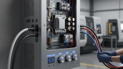
A three-phase to single-phase converter changes three incoming AC waveforms into one stable output waveform. Inside, the input terminals feed a rectifier bridge made from power diodes or controlled switches. This bridge changes AC into pulsing DC. A DC link capacitor then smooths the voltage and stores short bursts of energy. It can become very hot.

An inverter stage switches the DC rapidly through insulated power transistors. A control board sets the output voltage, frequency, and waveform. An output filter removes high-frequency switching noise before power reaches the load. Sensors monitor current, temperature, input loss, and DC-link voltage. Fuses, contactors, and surge protection add another safety layer. In practice, the neat diagram is not the whole story. Cable resistance, unbalanced input conditions, and motor starting currents can affect performance. I would check these details before trusting the rated capacity.

Tips: Match the converter’s output voltage and frequency with the equipment label. Leave ventilation space around the enclosure. Use a multimeter to verify isolation and polarity during commissioning. Never judge capacity from running watts alone. Starting demand may be several times higher. If the output hums, overheats, or fluctuates, stop testing and inspect the filter, grounding, and connections.

How Does a Three Phase to Single Phase Converter Work? - Key Components Inside a Three-Phase to Single-Phase Converter
Component Conversion Stage Primary Function How It Works Typical Electrical Role Key Design Consideration
Three-Phase Input Terminals Input Receive the three-phase AC supply and provide connection points for the converter. The three conductors carry AC voltages separated by approximately 120 electrical degrees. Common low-voltage systems may use line-to-line voltages such as 208 V, 230 V, 400 V, or 480 V, depending on the electrical system. The converter must be rated for the available voltage, frequency, phase sequence, and fault current.
Input Circuit Breaker or Fuse Protection Protect the converter, wiring, and upstream circuit from excessive current. The protective device opens the circuit during a short circuit or sustained overcurrent condition. Its current rating is selected from the converter input current, installation rules, and expected starting conditions. Protection must coordinate with conductor size and should allow normal inrush current without nuisance tripping.
Input Contactor or Disconnect Isolation Provide controlled switching and a means of safely isolating the converter. A contactor is controlled electrically, while a disconnect is operated manually for maintenance or emergency isolation. Used to start, stop, or isolate the power-conversion section. The device must be suitable for the system voltage, load current, switching duty, and applicable safety requirements.
Input EMI/RFI Filter Filtering Reduce conducted electromagnetic interference entering or leaving the converter. Capacitors and inductive elements attenuate selected high-frequency noise while allowing power-frequency current to pass. Improves electrical compatibility with nearby control, communication, and measurement equipment. Filter selection must consider leakage current, grounding method, voltage rating, and harmonic behavior.
Three-Phase Rectifier AC to DC Convert the incoming three-phase AC voltage into a pulsating DC voltage. A six-pulse diode or controlled silicon rectifier bridge directs current so that the most positive and most negative phase conductors feed the DC link at each instant. A six-pulse bridge produces six voltage pulses per input cycle and has a ripple frequency equal to six times the AC line frequency. It must withstand peak voltage, average current, repetitive current pulses, and fault energy.
DC-Link Capacitor Bank Energy Storage Smooth the rectified voltage and store short-term electrical energy. Capacitors charge near the peaks of the rectified waveform and supply current between peaks, reducing DC-link voltage ripple. Provides a relatively stable DC bus for the inverter stage. Capacitance, ripple-current rating, voltage rating, lifetime, and discharge time are critical parameters.
DC-Link Choke or Inductor Smoothing Limit current ripple and reduce the amplitude of input current pulses. The inductor opposes rapid changes in current, helping smooth the DC-link current and reduce stress on the rectifier and capacitors. Can improve current waveform quality and reduce DC-bus ripple in suitable converter designs. Inductance, saturation current, thermal loss, and physical size must match the converter power level.
DC-Bus Voltage Sensor Measurement Monitor the DC-link voltage for regulation and protection. A resistor divider, isolated sensor, or voltage transducer scales the high DC voltage into a signal suitable for the controller. Supports overvoltage, undervoltage, precharge, braking, and inverter-control functions. Isolation, accuracy, response time, insulation rating, and measurement noise must be controlled.
Inverter Power Switches DC to AC Convert the DC-link voltage into a controlled single-phase AC output. Power semiconductor switches, commonly IGBTs or MOSFETs in suitable voltage ranges, turn on and off rapidly according to a pulse-width-modulation pattern. A single-phase full bridge normally uses four controlled switches arranged in two switching legs. Switch voltage, current, switching frequency, conduction loss, switching loss, and short-circuit protection are important.
Gate-Drive Circuits Switch Control Deliver properly timed control signals to the inverter switches. Gate drivers amplify controller commands and provide the required gate voltage, isolation, dead time, and fault shutdown functions. Control switching transitions while preventing simultaneous conduction in the same inverter leg. Isolation, propagation delay, gate-drive power, noise immunity, and desaturation or overcurrent protection are key factors.
Output LC Filter Waveform Filtering Reduce high-frequency switching components in the inverter output. The inductor limits rapid current changes and the capacitor provides a low-impedance path for selected switching-frequency components. Produces a smoother single-phase voltage or current waveform for the connected load. Cutoff frequency, resonance damping, reactive current, load type, and voltage drop must be considered.
Output Transformer Optional Adaptation Provide galvanic isolation or change the single-phase output voltage. Alternating current in the primary winding produces magnetic flux that induces a proportional voltage in the secondary winding. May step voltage up or down and can establish a separately derived output system when appropriately designed. Power rating, insulation, regulation, inrush current, cooling, and frequency compatibility are essential.
Output Circuit Breaker or Fuse Output Protection Protect the single-phase output circuit and connected conductors. The protective device interrupts excessive output current caused by overloads or short circuits. Selected according to output voltage, continuous load current, conductor ampacity, and fault-clearing requirements. The rating must be compatible with the converter's overload capability and the load's starting current.
Control Processor Control Coordinate rectification, inverter switching, monitoring, and protective actions. A digital controller compares measured values with reference commands and adjusts the PWM duty cycle to regulate output voltage or frequency. May manage soft start, output regulation, current limiting, fault logging, and shutdown sequences. Control-loop bandwidth, computation time, firmware reliability, and fail-safe behavior affect performance.
Current Sensors Feedback Measure input, DC-link, or output current for control and protection. Shunts, current transformers, or Hall-effect sensors produce a signal proportional to current. Used for overload detection, current regulation, short-circuit response, and load monitoring. Sensor bandwidth, isolation, accuracy, offset, temperature drift, and peak-current capability are relevant.
Cooling System Thermal Management Remove heat generated by semiconductor switches, rectifiers, inductors, and other losses. Heat sinks, forced-air fans, heat pipes, or liquid cooling transfer heat away from power components. Maintains junction and enclosure temperatures within their specified operating limits. Cooling capacity, airflow, ambient temperature, dust protection, fan reliability, and acoustic noise must be evaluated.
Precharge Circuit Startup Limit inrush current when the DC-link capacitors are initially energized. A resistor temporarily restricts charging current; a bypass contactor or relay closes after the bus reaches a suitable voltage. Reduces stress on rectifier components, fuses, contactors, and capacitors during startup. Precharge timing, resistor pulse-energy rating, bypass operation, and failure detection are important.
Grounding and Protective-Earth Network Safety Provide a low-impedance path for fault current and reduce touch-voltage risk. Accessible conductive parts are bonded to protective earth in accordance with the applicable electrical installation requirements. Supports operation of protective devices during insulation faults. Bonding continuity, conductor sizing, insulation coordination, leakage current, and local regulations must be checked.
Note: A typical converter follows the sequence three-phase AC input → rectifier → DC link → single-phase inverter → output filter → single-phase AC output. Actual voltage, current, topology, efficiency, waveform quality, and protection features vary by converter design and application.

Factors Affecting Converter Performance and Application Safety

How Does a Three Phase to Single Phase Converter Work?

A three-phase-to-single-phase converter redirects power from three alternating inputs into one usable output. Its internal switching or transformer system balances voltage and current before supplying the single-phase load. Performance depends on more than rated output. Input voltage, frequency, load size, and phase imbalance all matter. A converter may operate normally during light use, then overheat when motors start.

Efficiency also changes with load type. Resistive heaters usually create steady demand. Pumps, compressors, and other motors draw high starting current. Poor ventilation can raise internal temperature quickly. Dust, loose terminals, and undersized cables create additional losses. These problems are easy to miss during a short inspection. A design may look correct on paper, yet perform poorly in a warm enclosure.

Tips: Check the output voltage with a calibrated meter before connecting equipment. Measure startup current, not only running current. Keep clear airflow around the converter. Use correctly rated fuses, grounding, and isolation devices. A qualified electrician should verify connections and protective settings. Never assume a converter is safe because its indicator light is on. Record temperature and voltage readings during realistic operation. This simple record often reveals unstable performance. Do not ignore small warning signs.